Research on the Characteristics of Communication Resonant Circuits? Wuhan UHV specializes in producing series resonant devices, with a wide range of product selection and professional electrical testing. When looking for series resonant devices, choose Wuhan UHV.
In circuits containing capacitors and inductors, if capacitors and inductors are connected in parallel, it may occur within a small period of time: the voltage of the capacitor gradually increases while the current gradually decreases; At the same time, the current of the inductor gradually increases, while the voltage of the inductor gradually decreases. And in another very short period of time: the voltage of the capacitor gradually decreases, while the current gradually increases; At the same time, the current of the inductor gradually decreases, while the voltage of the inductor gradually increases. The increase of voltage can reach a positive maximum value, and the decrease of voltage can also reach a negative maximum value. Similarly, the direction of current will also change in the positive and negative directions during this process, which is called electrical oscillation in the circuit.
A capacitor and an inductor are connected in series, the capacitor discharges, the inductor begins to have a reverse recoil current, and the inductor charges; When the voltage of the inductor reaches its maximum, the capacitor discharges completely, and then the inductor begins to discharge and the capacitor begins to charge. This reciprocating operation is called resonance. During this process, the inductor generates electromagnetic waves due to continuous charging and discharging.
The phenomenon of circuit oscillation may gradually disappear or remain unchanged. When the oscillation persists, we call it equal amplitude oscillation, also known as resonance.
The time during which the voltage across a capacitor or inductor changes by one cycle is called the resonance period, and the reciprocal of the resonance period is called the resonance frequency. The so-called resonant frequency is defined in this way. It is related to the parameters of capacitor C and inductor L, namely: f=1/2 π√ LC (Hz).
The amplitude frequency characteristic curve of LC circuit:

The method to find the resonance point is to observe the test voltage by increasing and decreasing the frequency in the frequency modulation interface. If the test voltage is highest at a certain frequency and low at other frequencies, then this point is the resonance point. Sometimes when the test voltage is lower than 2KV at a certain frequency such as f1, the frequency is not the true resonance point. Generally, only when the test voltage is greater than 2KV, the true resonance point can be found (if the load is too large, it may also be less than 2KV). After identifying the resonance point, raise the voltage at the voltage regulating interface until the desired value is reached.
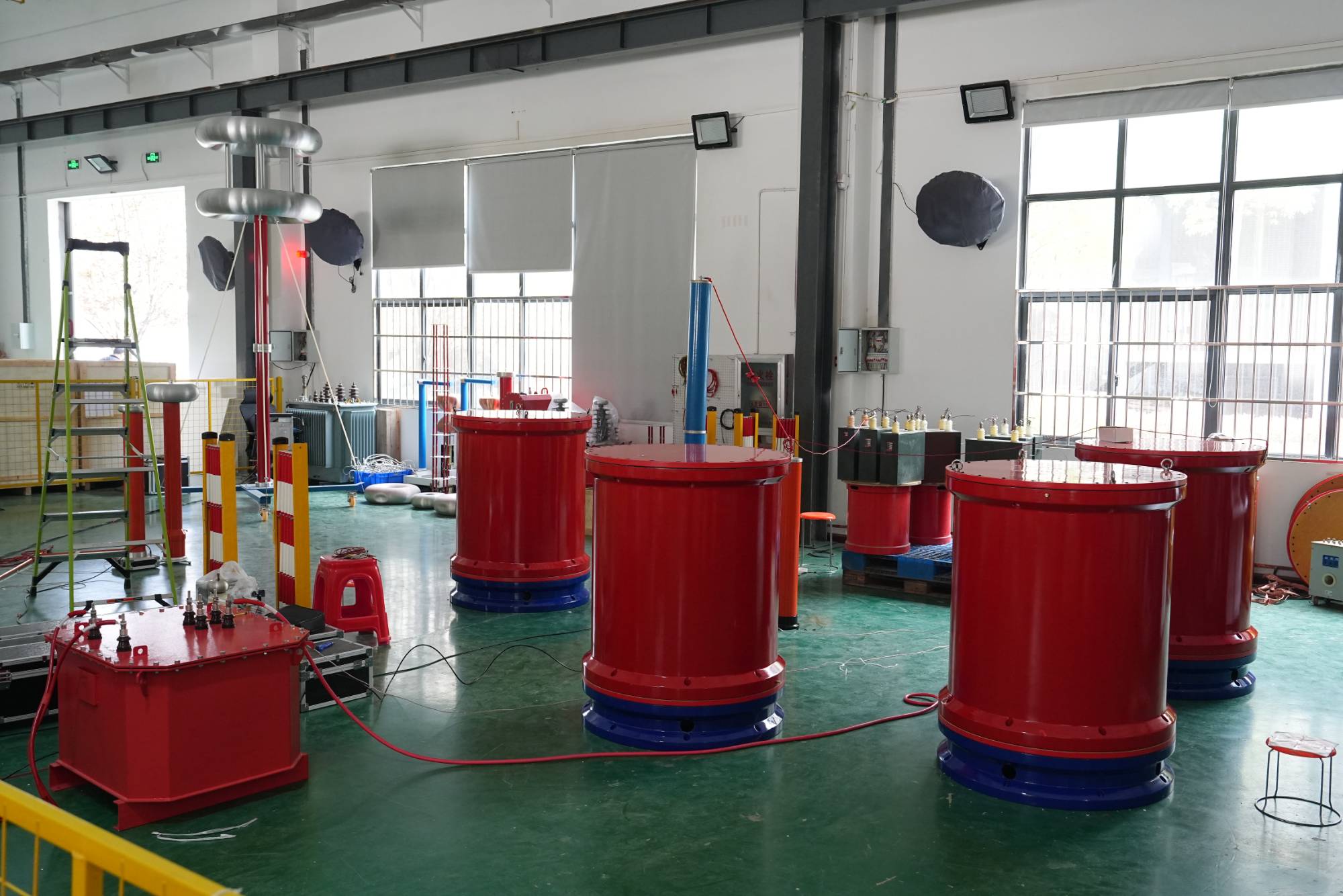
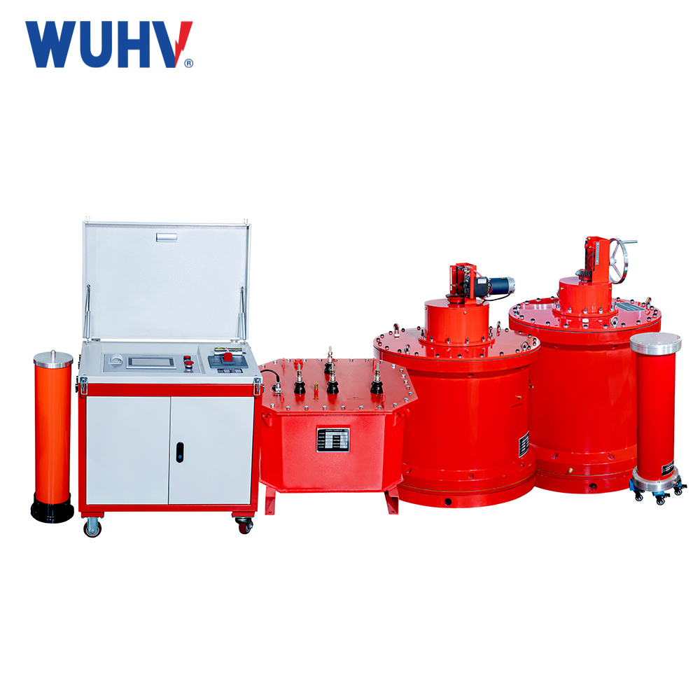
Ituseries resonance test device is composed of an isolation transformer, a frequency and voltage regulating power supply, an excitation transformer, a reactor, and a capacitive voltage divider. It uses a tuned inductor and load capacitor to generate power frequency series resonance and obtain the power frequency test voltage. It is suitable for AC withstand voltage testing of various large power transformers, power cables, steam turbines, hydro generators, and other capacitive equipment.
The method of using series resonance for AC withstand voltage testing is completely feasible. For the problems encountered in the experiment, adjusting the test frequency, selecting a deviation from the resonant frequency for testing, and adjusting the quality factor of the circuit are also effective methods. The aforementioned issues are only those discovered in current practical operations, and there may be other technical problems that need to be discovered and solved in practice in the future. At present, it is stipulated in the power regulations that AC withstand voltage must be tested for cables of 35KV and above. This requires us to constantly summarize our experience, learn from each other's strengths and weaknesses, gradually improve, and put forward higher requirements for new processes and materials. We should use effective scientific methods to cope with the increasingly developing new technologies


