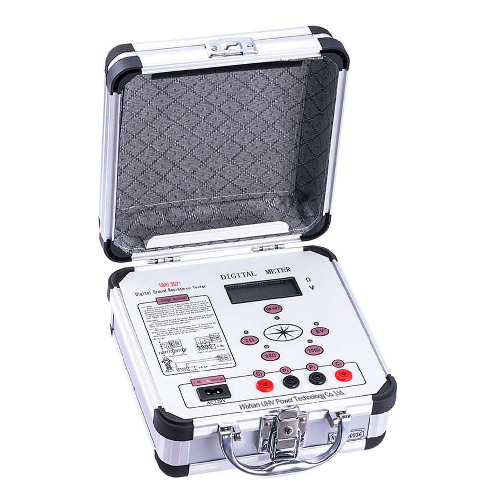
The grounding resistance tester under UHV power can help many power workers conduct various power tests more conveniently.

1. Connect the signal generator to the DC system:
Signal connection method of the signal generator: connect the red clip to the positive busbar; Connect the black clip to the negative busbar; Connect the yellow clip to the ground wire. After ensuring that the signal generator is connected correctly, turn on the power switch of the signal generator.
2. Output signal adapts to various voltage levels:
The signal generator adapts to DC systems of various voltage levels. When there is no grounding fault in the system, the "normal" indicator light is on. The grounding DC system voltage, positive grounding voltage, and negative grounding voltage of the LCD display. When a grounding fault occurs in the system, the signal generator automatically determines the grounding polarity. If the system is grounded to the positive pole, the "positive ground" indicator light of the signal generator will light up and flash when outputting a signal to the system. If the system is grounded to the negative pole, the "negative ground" indicator light of the signal generator will light up and flash when outputting a signal to the system. Simultaneously, the LCD displays positive ground voltage, negative ground voltage, and total impedance system's grounding insulation.
3. Preparation for fault detector detection:
Insert the clamp meter into the input plug of the "detector" clamp meter and turn on the power switch of the detector.
(For DC systems equipped with grounding line selection online monitoring devices, it is recommended to turn off the grounding line selection online monitoring device for easier detection.)
4. Testing begins:
Enabling 'communication' means that the detection circuit can receive synchronization signals, ensuring that the detection signal is synchronized with the output signal. If the "Communication" light is not on, it indicates that the communication between the signal generator and detector has failed.
Enable "Range": Enabling Range 1 means using Range 1 of the clamp gauge, while Enabling Range 2 means using the default Range 2 of the clamp gauge
5. When the positive and negative wires cannot be clamped together, it is recommended to use the "single clamp" detection method:
If the clamp gauge is grounded to the positive pole, connect the clamp gauge to the positive cable using the same testing method as described above; If the clamp gauge is grounded to the negative pole, connect the clamp gauge to the negative cable using the same testing method as described above.
6. When multiple circuit wires are bound together:
Connect the clamp gauge to the wire (note: the clamp must be completely closed), and the detection method is the same as the above method. If 'Non Grounding' is displayed, it indicates that the detected wire has no grounding fault; If 'Grounding' is displayed, it indicates that one or more circuits of the wire have a grounding fault. We will test the wires separately using the same method as described above.


